Overview
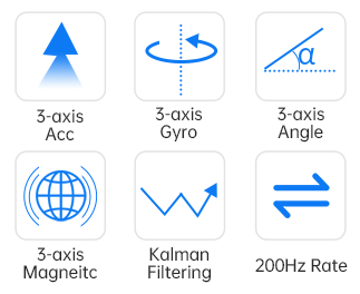
1. The module integrates high-precision gyroscopes, accelerometers, and geomagnetic field sensors, and uses high-performance microprocessors and advanced dynamics calculation and Kalman dynamic filtering algorithms to quickly solve the current real-time motion posture of the module.
2. The use of advanced digital filtering technology can effectively reduce measurement noise and improve measurement accuracy.
3. The module integrates an attitude solver, and with the dynamic Kalman filter algorithm, it can accurately output the current attitude of the module in a dynamic environment. The attitude measurement accuracy is 0.2°, the stability is extremely high, and the performance is even better than some professional inclination angles. instrument.
4. The Z-axis heading angle is added to the geomagnetic sensor filter fusion, which solves the cumulative error caused by the drift of the gyroscope integral in the 6-axis algorithm, and can output heading angle data stably for a long time. Note: Due to magnetic field detection, calibration is required before use, and when used, it needs to be at least 20cm away from magnetic interference areas, electronic equipment, magnets, speakers and other hard magnetic objects.
5. The module has its own voltage stabilization circuit, the working voltage is 3.3~5V, the pin level is compatible with 3.3V/5V embedded systems, and it is easy to connect.
6. Supports two digital interfaces, serial port and IIC. It is convenient for users to choose the best connection method. The serial port rate is adjustable from 4800bps to 230400bps, and the IIC interface supports the full speed 400K rate.
7. Maximum data output rate of 200Hz. The output content can be selected arbitrarily, and the output rate is adjustable from 0.2 to 200Hz.
8. Using stamp hole gold plating process, it can be embedded in the user's PCB board. Note: If you need to add a base plate or embed it into other PCB boards, no wiring should be done under the geomagnetic chip to avoid interfering with the magnetometer. 4-layer PCB board technology, thinner, smaller and more reliable.
Specifications
Parameters | Condition | Typical value |
Measuring range | ±16g | |
Resolution ratio | ±16g | 0.0005(g/LSB) |
RMS noise | Bandwidth=100Hz | 0.75~1mg-rms |
Static zero drift | Place horizontally | ±20~40mg |
Temperature drift | -40°C ~ +85°C | ±0.15mg/℃ |
Bandwidth | 5~256Hz |
Parameters | Condition | Typical value |
Measuring range | ±2000°/s | |
Resolution ratio | ±2000°/s | 0.061(°/s)/(LSB) |
RMS noise | Bandwidth=100Hz | 0.028~0.07(°/s)-rms |
Static zero drift | Place horizontally | ±0.5~1°/s |
Temperature drift | -40°C ~ +85°C | ±0.005~0.015 (°/s)/℃ |
Bandwidth | 5~256Hz |
parameters | Condition | Typical value |
Measuring range | ±2Gauss | |
Resolution ratio | ±2Gauss | 8.333nT/LSB |
parameters | Condition | Typical value |
Measuring range | X:±180° | |
Y:±90° | ||
Inclination accuracy | 0.2° | |
Resolution ratio | Place horizontally | 0.0055° |
Temperature drift | -40°C ~ +85°C | ±0.5~1° |
parameters | Condition | Typical value |
Measuring range | Z:±180° | |
Heading accuracy | 9-axis algorithm, magnetic field calibration, dynamic/static | 1°(Without interference from magnetic fields)【1】 |
6-axis algorithm, static | 0.5°(Dynamic integral cumulative error exists) 【2】 | |
Resolution ratio | Place horizontally | 0.0055° |
Note:【1】Please perform magnetic field calibration in the testing environment before use to ensure that the sensor is familiar with the magnetic field in the environment. During calibration, please stay away from magnetic interference.
【2】In some vibration environments, there will be cumulative errors. The specific errors cannot be estimated and are subject to actual testing.
Application


Download
Product InformationVideo